 There is a fundamental physical limit on the ability of lasers to focus on their targets. It is called diffraction. To understand diffraction, you need to understand the behavior of waves.
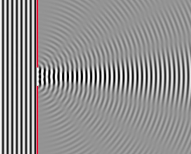
When a freely propagating wave encounters a barrier, it can curve around the barrier. Think of ripples on the surface of a still pond passing a post sticking out of the water. Similarly, a wall with a single opening will let the wave through the opening, but the edges of the wave will curve out toward the sides, causing the transmitted wave to spread out. This phenomenon is known as diffraction. It happens with every kind of wave in nature. Light is a wave in the electromagnetic field, so light undergoes diffraction. It does not even require an object in the path of the wave, any beam of waves has a tendancy to spread out to the sides due to this effect.
The smaller the wavelength of a wave in comparison to the size of the obstruction or opening, or the width of the beam, the less the wave diffracts. Since visible light has a very small wavelength, this is why light seems to travel in straight lines. It takes very narrow objects, such as hairs or thin scratches, to get noticable diffraction. This is easy to demonstrate with a laser pointer in a darkened room. Shine the beam at a wall. Now put a hair in the beam. You will see a streak appear on the wall through the laser dot perpendicular to the hair. The streak is the light diffracting around the hair.
When a laser beam is propagating freely, it will naturally tend to expand. This means that if you try to focus the beam down to a tiny point at a distant target, the beam might spread out to a much larger spot by the time it gets there. The amount the beam expands depends on the ratio of the initial width of the beam to the wavelength of the beam. In fact, we can determine the smallest possible spot size into which you can focus the beam: if we denote the diameter of the mirror, lens, or other opening in the laser or focusing element as D, the wavelength of the light as λ, and the distance to the target as R, then the diameter of the smallest spot, S, is given by
S = 1.2 R λ / D.
Make sure you use the same units for R, λ and D (this will give S in that unit as well). The term 1.2 λ / D is sometimes called the divergence angle θ (even though the beam will be converging if S < D). With this terminology,
S = R θ.
For example, a laser that emits 5×10⁻⁷ meter wavelength light (or 0.5 microns, this puts it in the visible green) that is focused through a 0.1 meter lens at a target 1000 meters (1 km) away will have a minimum spot size of 6×10⁻³ meters (6 millimeters) and a divergence angle of 6×10⁻⁶ radians.
The above formulas are only valid when R is much larger than D. The details of near field diffraction are too complex to cover here, although you will not be too far wrong using the formulas as long as R > D.
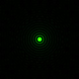
Below, the intensity profile of a beam after leaving the death ray is shown, followed by the diffraction pattern at tight focus at the target. A table gives the following information:
- The highest intensity in the diffraction pattern, relative to the maximum intensity of the first example shown.
- The radius, in pixels of the image, of the spot size parameter R λ / D. Where not appropriate, this row is not displayed.
- The radius, in pixels, that contains 70% of the beam power, 80% of the beam power, 90% of the beam power, and 95% of the beam power. You will see that some aperture designs scatter some of the light far beyond the spot size.
In the table, it is assumed that the same amount of power passes through each aperture shown. Where the aperture is partially obscured, it is assumed that the power remaining in the beam after encountering the obstruction is the same as the standard power used for full apertures. In other words, the total power from the intensity profile shown in the picture is the same for all cases. The picture brightness is re-scaled for ease of viewing, and does not necessarily reflect, for example, that the intensity of light will be less across a large aperture than a small one when both direct the same amount of power.
|
| Beam Profile at Aperture | Beam Profile at Focus | Distribution | Notes
|  | 
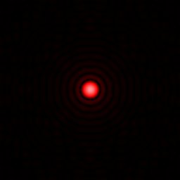
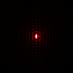
| | Peak Intensity: | 1.0
| | R λ / D: | 10
| | 70% of power within: | 6.5
| | 80% of power within: | 8.2
| | 90% of power within: | 18
| | 95% of power within: | 38
|
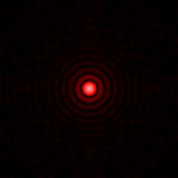
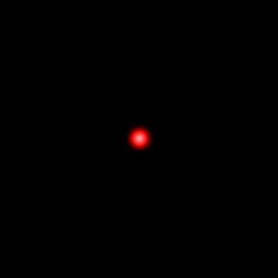
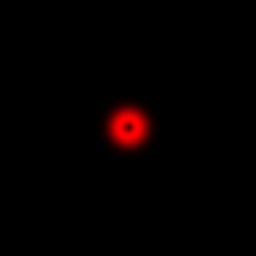
| This shows the pattern of light produced by the diffraction of a beam of uniform intensity through a circular aperture. The central disk has a diameter of S = 1.2 R λ / D, with rings of lower intensity fading away with distance. This intensity pattern is called an Airy pattern. The center spot has a radius of 12 pixels.
|  | 
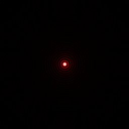
| | Peak Intensity: | 4.0
| | R λ / D: | 5
| | 70% of power within: | 2.9
| | 80% of power within: | 3.8
| | 90% of power within: | 8.7
| | 95% of power within: | 19
|
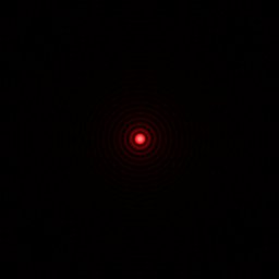
| If the aperture is made larger, the focus becomes tighter.
|  | 
| | Peak Intensity: | 1.7
| | R λ / D: | 7.7
| | 70% of power within: | 4.8
| | 80% of power within: | 6.1
| | 90% of power within: | 14
| | 95% of power within: | 29
|
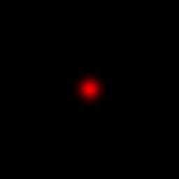
| Using shorter wavelength light also makes the focus tighter.
|  | 
| | Peak Intensity: | 2.7
| | R λ / D: | 7.2
| | 70% of power within: | 3.8
| | 80% of power within: | 4.8
| | 90% of power within: | 11
| | 95% of power within: | 23
|
| Here the wavelength is even shorter.
|  | 
| | Peak Intensity: | 2.0
| | 70% of power within: | 4.2
| | 80% of power within: | 4.8
| | 90% of power within: | 6.0
| | 95% of power within: | 7.0
|
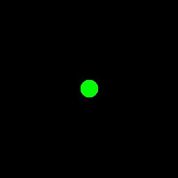
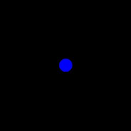
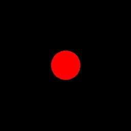
| If the beam profile at the aperture falls off smoothly instead of sharply, the rings are reduced. Here, the beam profile is a mathematical function called a Gaussian. This beam profile results in the minimum spread at the focus - and the beam profile at the focus is still a Gaussian without any rings at all. A Gaussian beam is sometimes also called the TEM00 mode.
|  | 
| | Peak Intensity: | 1.5
| | 70% of power within: | 6.3
| | 80% of power within: | 7.0
| | 90% of power within: | 8.0
| | 95% of power within: | 9.0
|
| Gaussian profile beams are not the only ones whose profile shape is not affected by diffraction. Here is a rectangular TEM10 mode.
|  | 
| | Peak Intensity: | 0.95
| | 70% of power within: | 9.1
| | 80% of power within: | 9.8
| | 90% of power within: | 11
| | 95% of power within: | 12
|
| This is a rectangular TEM12 mode.
|  | 
| | Peak Intensity: | 0.74
| | 70% of power within: | 6.3
| | 80% of power within: | 7.0
| | 90% of power within: | 8.0
| | 95% of power within: | 9.0
|
| And this is the cylindrical TEM01* "doughnut" mode.
|  | 
| | Peak Intensity: | 0.80
| | 70% of power within: | 12
| | 80% of power within: | 13
| | 90% of power within: | 14
| | 95% of power within: | 15
|
| And the cylindrical TEM13 mode.
|  | 
| | Peak Intensity: | 0.93
| | R λ / D: | 10
| | 70% of power within: | 6.3
| | 80% of power within: | 7.4
| | 90% of power within: | 9.0
| | 95% of power within: | 12
|
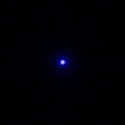
| A pure Gaussian never truely falls away to zero. Clearly, you can never achieve this profile at a real aperture, you need to cut it off someplace. Here is shown a Gaussian beam clipped by the edge of an aperture. You still get ringing, but not as much. The center spot is a bit larger than if the beam were uniform at the aperture, with a 14 pixel radius, but the central spot is also significantly brighter so that the light is more concentrated overall.
|  | 
| | Peak Intensity: | 0.88
| | R λ / D: | 10
| | 70% of power within: | 6.8
| | 80% of power within: | 8.2
| | 90% of power within: | 18
| | 95% of power within: | 58
|
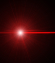
| Here, a beam encounters a narrow barrier obscuring 7% of the area of the primary mirror. Note how the diffraction around the barrier is perpendicular to the direction of the barrier. The listed peak intensity and radii do not account for the portion of the beam that was blocked. In fact, the power scattered by diffraction due to a barrier is equal to the power of the beam directy shadowed by the barrier. In this case, the central spot loses 7% of its power from shadowing, and an additional 7% of its power is scattered away by diffraction, so the total power level of the central spot is reduced to 86% of its original power.
|  | 
| | Peak Intensity: | 0.82
| | R λ / D: | 10
| | 70% of power within: | 8.0
| | 80% of power within: | 18
| | 90% of power within: | 44
| | 95% of power within: | 87
|
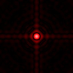
| The aperture of the beam pointer that directs the death ray beam is often partly obscured by secondary mirrors and supports, leading to additional diffraction (not to mention that some of the beam is directly blocked - in this example, 18% of the primary mirror area is obscured).
|  | 
| | Peak Intensity: | 0.79
| | R λ / D: | 10 × 10
| | 70% of power within: | 7.6
| | 80% of power within: | 10
| | 90% of power within: | 23
| | 95% of power within: | 45
|
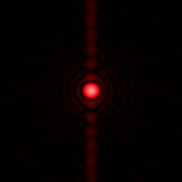
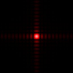
| Here is the diffraction pattern through a square aperture. The total area of the aperture is 20% greater than for the original circular aperture in the top panel.
|  | 
| | Peak Intensity: | 0.39
| | R λ / D: | 10 × 20
| | 70% of power within: | 13
| | 80% of power within: | 17
| | 90% of power within: | 36
| | 95% of power within: | 62
|
| As the aperture gets narrower in one direction, diffraction causes the beam to spread out more in that direction.
|  | 
| | Peak Intensity: | 2.0
| | R λ / D: | 10
| | 70% of power within: | 6.3
| | 80% of power within: | 8.2
| | 90% of power within: | 18
| | 95% of power within: | 38
|
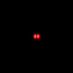
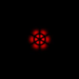
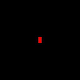
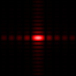
| Here is the diffraction through two apertures whose beams are in phase with each other. The combined diffraction pattern can be thought of as interference between the individual diffraction patterns producing a pattern of dark bars over the center dot and rings. The bright areas between the bars are higher intensity than for a single aperture of the same diameter, but are no higher intensity than a single aperture with twice the area putting out the same total power.
|  | 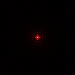
| | Peak Intensity: | 5.0
| | R λ / D: | 10
| | 70% of power within: | 7.1
| | 80% of power within: | 8.6
| | 90% of power within: | 18
| | 95% of power within: | 37
|
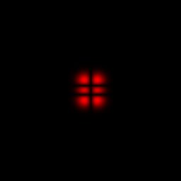
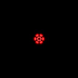
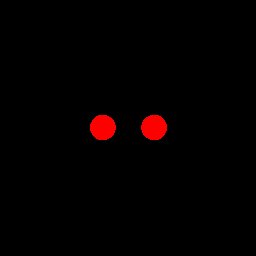
| If you add more and more apertures which are in phase, you get a phased array. The interference between the light from the different apertures concentrates the light in a smaller central spot. The closer the array elements are together, the better they interfere to produce a compact bright central spot. In fact, the best arrangement is to use a single circular aperture with a combined area equal to the area of the apertures in the array. For this reason, death ray designers usually forgo phased arrays and concentrate on large mirrors. If the light from the apertures is not in phase, it adds incoherently and the difraction pattern at the focus is the same as for a single aperture of that size (although the intensities of the light from the individual spots do add).
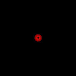
|  | 
| | Peak Intensity: | 5.0
| | R λ / D: | 4.5
| | 70% of power within: | 2.5
| | 80% of power within: | 3.4
| | 90% of power within: | 7.7
| | 95% of power within: | 17
|
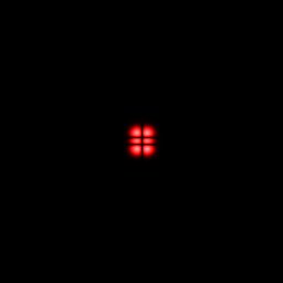
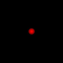
| Here we show a single large aperture with the same total area as the five smaller apertures in the phased array above, showing how this concentrates the light better.
|
|
A note for the mathematically inclined: the beam profile at the focus is the 2D Fourier transform of the beam profile at the aperture.
Back to main death ray page
|

 There is a fundamental physical limit on the ability of lasers to focus on their targets. It is called diffraction. To understand diffraction, you need to understand the behavior of waves.